During a fire emergency, reliable sources of water can mean the difference between life and death. This is why the National Fire Protection Association (NFPA) outlines fire hydrant testing that measures real-world pressure and flow in a city’s water distribution system.
In this blog, we discuss how often flow tests are needed to ensure hydrants will work as expected during a fire. We also dig into the details of what should be done to ensure a water supply meets firefighting requirements.
Regular fire hydrant testing ensures the ability to provide water at an acceptable pressure and flow rate for public health and firefighting operations. Most jurisdictions also require hydrant flow tests to design fire sprinkler systems for commercial or residential structures.
The 2022 edition of NFPA 291: Recommended Practice for Fire Flow Testing and Marking of Hydrants (4.2.2) recommends that fire hydrants should maintain a residual pressure of 20 psi (pounds per square inch), or 1.4 bar, for effective firefighting, as well as to prevent backflow that could contaminate the public water supply.
NFPA 291 stipulates hydrant flow tests every five years to ensure that changing conditions in the piping and system demands won’t impede hydrants’ ability to deliver water.
From the 2022 edition of NFPA 291
4.15.1 Public fire hydrants should be flow tested every 5 years to verify capacity and marking of the hydrant.
In the explanation that accompanies the section (A.4.15.1), NFPA clarifies the section’s intent. It states that it does not mean to mandate routine five-year testing of every hydrant—especially if there is no pressing need to test a specific hydrant or if test data less than five years old is available from an adjacent hydrant on the same grid.
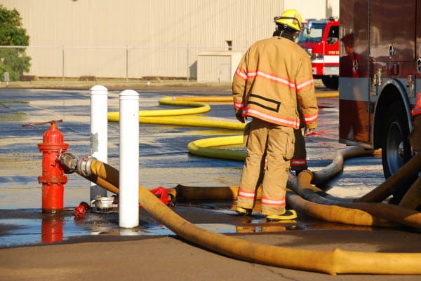
Performed by city officials or professional contractors, fire hydrant testing verifies the performance of a city’s water distribution system, determining the pressure and rate of flow available at various locations. It measures static (non-flowing) and residual (flowing) pressure, as well as the rate of discharge in gallons per minute (GPM) of each fire hydrant.
The data that’s collected is used for two important purposes:
Besides delivering peace of mind that hydrants will work in an emergency, hydrant flow tests enable municipalities to color-code their fire hydrants according to their strength of output. The colors categorize hydrants by the GPM of their flow. For instance, the color-coding scheme recommended by NFPA 291 (5.1) and The American Water Works Association says light blue hydrants have a capacity of 1,500 GPM or more (“very good flow”) and red hydrants have a capacity below 500 GPM (“inadequate”).
This system allows fire departments to assess their water resource capabilities quickly when arriving on the scene of an emergency. You can check out our previous blog to learn more about fire hydrant colors and what they mean.
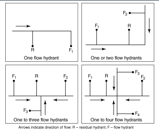
Specific instructions for conducting fire hydrant testing can be found in NFPA 291’s Chapter 4, “Flow Testing.” NFPA 291 guidelines require identifying a residual (test) hydrant to measure static and residual pressure, as well as one or more flow hydrants.
Static pressure represents the pressure at a given point under normal distribution system conditions. It is measured at the residual hydrant with no hydrants flowing. Residual pressure is the pressure that exists in the water distribution system while water is flowing. It is measured at the residual hydrant at the same time flow readings are taken at the flow hydrants.
To determine how many flow hydrants are needed, keep in mind that NFPA 291 recommends flowing enough water to provide at least a 10% drop in residual pressure compared to the static pressure (4.4.6). Further, it states that testers may need to “declare an artificial drop in the static pressure of 10 percent” in “water supply systems where additional municipal pumps increase the flow and pressure as additional test hydrants are opened.” NFPA has updated this guidance from the 2019 edition, which recommended flowing the total demand necessary for firefighting purposes during the test, or enough water to provide at least a 25% drop in residual pressure compared to the static pressure. (In 2018, Sprinkler Age noted that the 25% drop was not necessary for a hydrant flow test used to design a fire suppression system.)
Both editions say that if the mains are small and the system is weak, only one or two hydrants need to flow (2022: 4.4.8/2019: 4.3.7). If the mains are large and the system is strong, as many as eight flow hydrants may be required (2022: 4.4.9/2019: 4.3.8).
Before starting a flow test, it’s important to notify the water company or water authority. Opening a hydrant could disrupt normal operating conditions for the water distribution system in an area.
A water diffuser and sock can also help prevent damage to landscaping and roadways, and redirect water to stop ice patches from forming on certain surfaces in the winter. It’s wise to check that local drains are not blocked by leaves or other debris to prevent water backup. Portable radios can also make testing easier when more than one hydrant flows.
The 2022 edition of NFPA 291 (4.3.1) now suggests conducting hydrant flow tests during periods of “periods of peak demand, based on knowledge of the water supply and engineering judgment,” which is an update from the 2019 edition’s guidance to do it during periods of “ordinary demand” (NFPA 2019: 4.2.1) That’s likely because many fire protection professionals recommend performing flow tests during peak morning hours to reflect the worst-possible scenario during an emergency. Street pressures can fluctuate as much as 10 psi in the morning, compared to later in the day when demand is typically less.
Be prepared to record the following information during the test:
Here’s an overview of how to perform a hydrant flow test. Read this carefully: It is not meant as a comprehensive step-by-step guide. Testers should always consult their local authority having jurisdiction (AHJ) and fire department guidelines for the most accurate information.
We get into the equations of step 10 in the next section, but you can first watch this video to witness a hydrant flow test:
As mentioned above, the tester needs to gather key information to run two equations in sequence.
The first equation determines the flow (gpm) from the tested fire hydrants based on the pitot gauge pressure readings. A version of it is found in section 4.93 of NFPA 291:
Q = 29.83 * c * d 2 * √P
Q = discharge; the gallons flowing during the test (gpm)
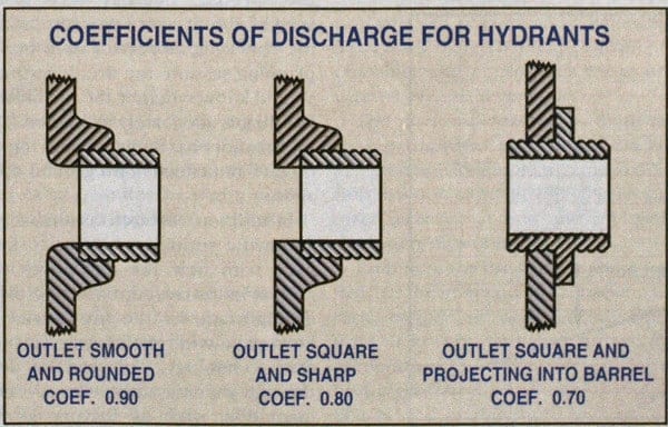
c = coefficient of discharge, which represents friction loss. It’s determined by assessing the shape of the transition between the vertical barrel of the hydrant and the horizontal outlet. Most hydrants have a smooth and rounded transition resulting in a .90 coefficient of discharge but not all of them (as shown below):
d = diameter of the outlet
P = the pressure reading at the pitot gauge during the test (PSI)
You can read a more in-depth look at calculating this gpm value plus access a handy calculator in our previous blog: “Pitot Gauges: How Do I Calculate the PSI to GPM Conversion?”
The second formula estimates the “flow predicted at desired residual pressure,” which is sometimes called the “available fire flow” (AFF). This essential equation is found in section 4.12.1.2 of NFPA 291, but here is a version with more steps broken out:
QR = Q * (((S – 20) 0.54 ) ÷ ((S – R) 0.54 )))
QR = flow predicted at desired residual pressure/available fire flow
Q = the discharge (gpm) measured during the test (the result of the first equation)
S = the static pressure measured during the test
20 = the amount of minimum pressure (in psi) required for most municipal water supplies to prevent backflow and achieve fire protection objectives.
(NFPA 291 calls the “S – 20” calculation above “hr,” which equals “pressure drop to desired residual pressure”)
R = the residual pressure measured during the test
(NFPA 291 calls the “S – R” calculation above “Hf,” which equals the “pressure drop measured during test”)
0.54 = a constant within the Hazen-Williams equation
After conducting a hydrant test, testers plug in their measurements to the two formulas above, completing one after the other.
The middle of a fire emergency is not the right time to find out that fire hydrants or sprinklers don’t have enough flow and pressure. Regular fire hydrant testing ensures that this vital equipment works as intended. And when requirements aren’t up to par, these assessments enable repairs to be proactively scheduled so problems can be dealt with before they could lead to loss of life or property.
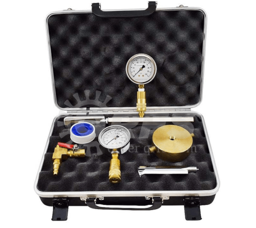
Ready to perform a hydrant flow test? Be sure to browse our full selection of pitot gauge kits, flow test accessories, and pressure gauges.
If you have questions or need help ordering, call us at +1 (888) 361-6662 or email support@qrfs.com.